
Ensuring Battery Management System (BMS) Safety in LiFePO4 Packs
A technical guide to LiFePO4 BMS safety, covering active balancing, thermal management, cell-level diagnostics, and international compliance.
Deployment of lithium iron phosphate (LiFePO4) energy storage systems (ESS) across commercial and industrial (C&I) sectors faces stringent operational boundary requirements. While LiFePO4 chemistry exhibits inherent thermal stability compared to nickel-manganese-cobalt (NMC) variants, unmitigated cell imbalance, thermal propagation, and control topology flaws still threaten asset longevity.
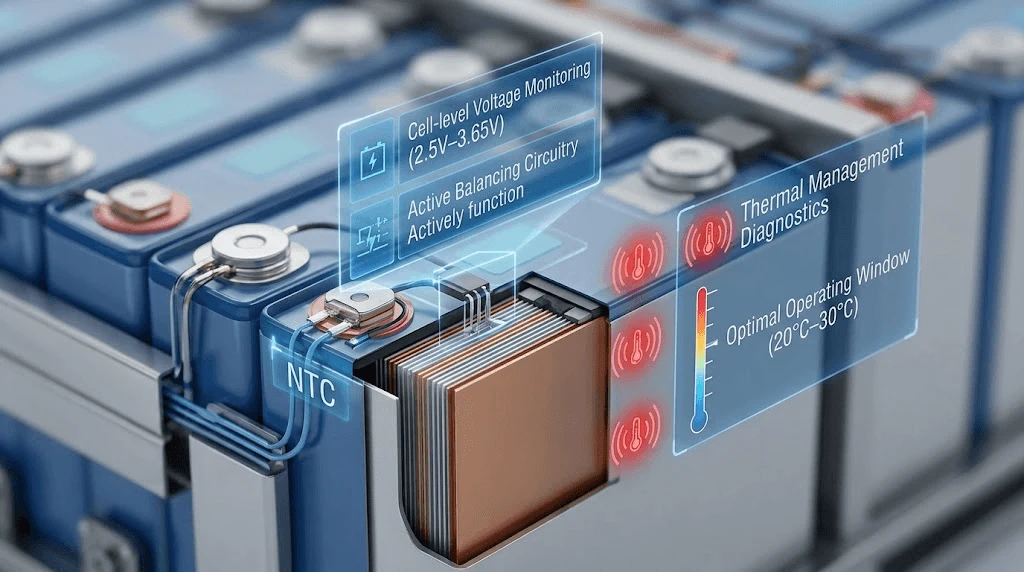
A single cell operating outside its optimal voltage window (2.5V to 3.65V) can induce localized degradation, reducing usable pack capacity by up to 35% over 1,500 cycles. Furthermore, inadequate thermal monitoring risks localized heating events, leading to unexpected system tripping and downtime.
To protect long-term levelized cost of storage (LCOS), EPC contractors and project managers require robust, multi-layered Battery Management System (BMS) architectures. This analysis outlines the primary control mechanisms, balancing topologies, and diagnostic protocols essential for utility-grade LiFePO4 pack stability.
Technical Analysis: Core Safety Mechanisms & Architecture
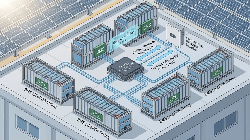
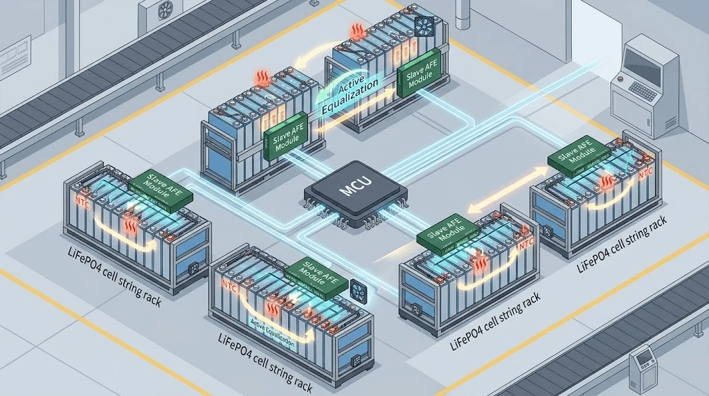
A resilient BMS relies on a distributed master-slave architecture. The Analog Front-End (AFE) ICs directly monitor cell groups, passing telemetry to the central MCU via isolated CAN bus interfaces.
1. Cell-Level Voltage Monitoring & Threshold Calibration
Precision voltage sensing requires dedicated AFE channels with a signal tolerance of < ±2 mV. Standard LiFePO4 discharge curves present an extremely flat voltage plateau between 30% and 80% State of Charge (SOC), making open-circuit voltage (OCV) methods insufficient for state estimation. A high-grade BMS combines Coulomb counting with extended Kalman filter (EKF) algorithms to track SOC accurately within ±2. The protection parameter thresholds must be hardware-enforced at the AFE layer to ensure execution independent of MCU firmware latency:
Over-Voltage Cutoff (OVC): 3.65 V (Cell level) / Delay: <10 ms
Over-Voltage Recovery: 3.45V
Under-Voltage Cutoff (UVC): 2.50V (Cell level) / Delay: <10ms
Under-Voltage Recovery: 2.80V
2. Active Cell Balancing Topologies
Passive balancing burns excess energy through shunt resistors as heat, typically capped at low currents (50mA to 100mA). For high-capacity commercial packs (>100Ah), active balancing is required.
Active systems utilize bi-directional DC-DC converters or capacitive switching networks to transfer charge from higher-voltage cells to lower-voltage cells during both charge and discharge cycles. By enabling balancing currents between 2A and 5A, active topologies mitigate capacity loss from capacity variance across large cell strings, improving usable energy yield over the asset lifecycle.
3. Thermal Management & Predictive Diagnostics
Temperature variation across a module should not exceed 3℃. The BMS utilizes Negative Temperature Coefficient (NTC) thermistors configured at a minimum ratio of 1 sensor per 4 series cells, plus additional probes attached to power MOSFETs and main busbars.
Integrated firmware continuously calculates thermal gradients dT/dt. If a localized cell temperature rate of change exceeds 1℃/min, the system triggers diagnostic alerts before reaching absolute over-temperature cutoffs (55℃ charge /60℃ discharge).
Industry Standards & Impact on LCOS
Selecting an industrial-grade BMS directly alters project financials by extending lifecycle throughput and reducing operational expenditure (OpEx).
|
Parameter / Feature |
Standard Commercial BMS |
Advanced Industrial BMS Architecture |
|
Balancing Architecture |
Passive (50 mA−100 mA) |
Active Bi-Directional (2 A−5 A) |
|
Voltage Sensing Accuracy |
±10 mV |
±2 mV |
|
Communication Protocols |
Basic RS485 |
Dual CAN bus / Modbus TCP / SNMP |
|
Fault Reaction Time |
<100 ms |
<2 ms (Hardware Interrupt) |
|
Thermal Sensing Ratio |
1 Probe per 16 Cells |
1 Probe per 4 Cells + Busbar Monitoring |
|
Design Life Cycle |
3,000 Cycles (80% SOH) |
6,000–8,000 Cycles (80% SOH) |
LCOS Impact Analysis
By maintaining cell imbalance under 10mV across an 8,000-cycle lifetime, an active-balancing BMS prevents premature string shutdown caused by isolated low-voltage cells. This capability reduces the Levelized Cost of Storage (LCOS) by:

· Usable Capacity Preservation: Prevents the "weakest link" effect, keeping string capacity near nominal ratings.
· Reduced Replacement Cycles: Extends overall pack service life beyond 10 years without requiring mid-life cell module replacements.
System Integration & Compatibility
A compliant BMS must seamlessly interface with upstream power conversion systems (PCS) and solar charge controllers.
When deploying commercial storage solutions like the 25.6V 100Ah Energy Storage Module, industrial communications depend on low-latency CAN bus 2.0B and Modbus RTU protocols. The BMS transmits dynamic operational limits to the inverter in real time:
Charge Current Limit (CCL): Dynamically adjusted based on maximum cell voltage and internal temperature.
Discharge Current Limit (DCL): Adjusted based on minimum cell voltage, temperature, and present SOC.
This closed-loop communication forces the inverter to throttle output before thermal or voltage limits are breached, preventing hard system shutdowns under heavy load profiles.
Quality Control & Global Compliance
Industrial safety assurance requires verified adherence to global testing standards.
UL 1973: Safety standard for batteries used in stationary applications. Verifies structural integrity, cell containment, and electrical safety under fault conditions.
IEC 62619: Mandates functional safety tests for industrial lithium batteries, including thermal runaway propagation testing and control unit software safety checks.
UN 38.3: Transport safety testing, including altitude simulation, thermal shock, vibration, impact, external short circuit, and forced discharge.
Manufacturing quality control must incorporate automated end-of-line (EOL) testing. Every BMS board undergoes short-circuit protection verification, calibration checks across all measurement channels, and burn-in conditioning under elevated thermal conditions (50℃) before final assembly.
FAQ
1. How does the BMS prevent thermal runaway propagation under short-circuit conditions?
The BMS utilizes a two-tier defense strategy: primary short-circuit hardware interrupts trigger ultra-fast solid-state switch/MOSFET disconnections within < 100 microseconds when current thresholds are breached. If you use a mechanical relay or contactor topology, ultra-rapid semiconductor fuses provide secondary physical isolation. Additionally, the control firmware monitors dT/dt vectors to detect internal shorting before gas venting or thermal propagation occurs.
2. What are the logistics and safety requirements for shipping high-capacity LiFePO4 packs overseas?
All packs must be certified under UN 38.3 regulations and shipped at a State of Charge (SOC) between 30% and 50%. Packs require UN-certified hazard packaging (Class 9 dangerous goods) featuring reinforced inner insulation, short-circuit terminal protection, and moisture-sealed inner wrapping. The BMS must be set to a low-power "Deep Sleep Mode" during transit to limit self-discharge to < 0.5% per month.
3. What are the boundaries for custom OEM/ODM BMS firmware adaptations for specific inverter protocols?
Customization boundaries include modification of CANbus/RS485 frame structures, mapping custom Modbus register addresses, adjusting dynamic SOC/SOH calculation algorithms, and configuring custom temperature/voltage trip curves. Physical layer modifications allow options between solid-state MOSFET switching or external contactor driver circuits based on system voltage limits (up to 1000 VDC. Standard engineering turnaround for firmware protocol adaptations is typically 2 to 3 weeks.
Contact our engineering team within 48 hours for a customized commercial PV and energy storage system layout and a detailed BOM quote.