
Understanding IEC/UL Certifications for Bi-Directional Inverters
Master IEC and UL compliance for bi-directional inverters. Optimize grid integration, anti-islanding safety, and ROI for industrial solar systems.
Introduction
Global EPC contractors and energy project developers frequently encounter regulatory roadblocks, grid code non-compliance penalties, and unexpected thermal derating during utility-scale or commercial solar-plus-storage deployments. In multi-megawatt installations, failing regional grid interconnect standards like IEEE 1547, UL 1741 SA, or IEC 62109 can delay grid-tie approvals by months, inflating capital expenditure and stalling return on investment (ROI). Furthermore, inadequate electromagnetic compatibility (EMC) filtering introduces harmonic distortions that threaten microgrid stability under high-penetration renewable scenarios.
This technical guide outlines the precise engineering criteria required to evaluate bi-directional inverters against stringent international IEC and UL standards. We analyze advanced circuit topologies, hardware-level safety validation, active anti-islanding algorithms, and EMC compliance metrics. By understanding these regulatory benchmarks, procurement teams and project engineers can secure reliable grid interconnection, minimize technical friction across solar panels, mounting structures, and LiFePO4 battery storage, and safeguard long-term plant performance.
Technical Analysis and Core Mechanisms
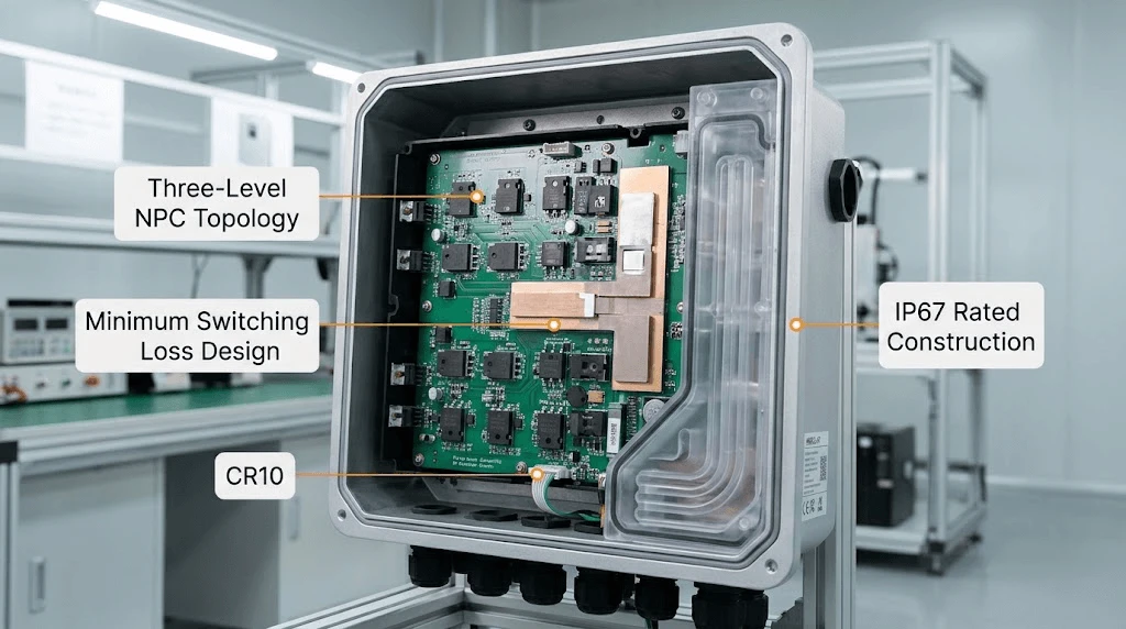
Modern bi-directional inverters deployed in commercial and industrial (C&I) microgrids rely on advanced three-level Neutral Point Clamped (NPC) topologies to minimize switching losses and maintain high conversion efficiencies of up to 98.4%.
●Thermal Management & Enclosure Integrity: To withstand harsh operating environments without power derating up to 50°C, industrial-grade units utilize intelligent forced-air cooling coupled with IP65/IP67 ingress protection, isolating sensitive printed circuit boards (PCBs) from moisture and particulate contamination.
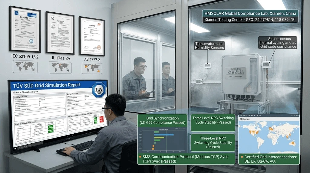
●Electromagnetic Compatibility (EMC): Compliance with IEC 61000-6-2 and IEC 61000-6-4 ensures that high-frequency switching operations do not generate electromagnetic interference that disrupts auxiliary substation telemetry or supervisory control and data acquisition (SCADA) networks.
●Anti-Islanding Protection: Hardware-redundant active frequency drift (AFD) and reactive power injection algorithms detect grid loss within 2 seconds, immediately disconnecting the inverter to protect utility line technicians and prevent unsynchronized re-closure events.
Industry Standards and ROI Impact
Procuring certified hardware directly dictates the levelized cost of electricity (LCOE) by eliminating costly retrofits and regulatory fines. Below is a comparative parameter breakdown between standard commercial units and HMSOLAR certified bi-directional inverter systems.
|
Technical Parameter |
Standard Commercial Inverter |
HMSOLAR Certified Bi-Directional Inverter |
|
Max Conversion Efficiency |
97.60% |
98.40% |
|
Total Harmonic Distortion (THD) |
< 3.0% |
< 1.5% |
|
Grid Standard Compliance |
Regional Only (CE/EN) |
IEC 62109-1/-2, UL 1741 SA, IEEE 1547 |
|
Thermal Derating Threshold |
40Ā°C |
50Ā°C |
|
BMS Communication Protocol |
Proprietary RS485 |
Standardized CAN 2.0 / Modbus TCP |
|
Salt Mist Resistance Rating |
IEC 61701 Severity 3 |
IEC 61701 Severity 6 (Severe Coastal) |
ROI Analysis
Integrating certified bi-directional inverters directly reduces balance-of-system (BOS) expenses. The reduction in total harmonic distortion (THD < 1.5%) minimizes transformer heating losses, recovering approximately 0.4% to 0.7% of annual generation that is typically lost as thermal waste. Combined with an extended 10-to-20-year linear performance warranty and zero-downtime grid compliance, project payback periods across C&I microgrid installations are shortened by 1.2 to 1.8 years.
System Integration and Compatibility
Successful execution of solar-plus-storage projects requires seamless physical and electrical synchronization across all balance-of-system components available at hemaosolarpv.com/ongrid-bidirectional.
●PV Module Synergy: The wide MPPT voltage range (200V to 1000V) accommodates high-current 720W N-Type TOPCon solar panels without clipping losses during peak irradiance intervals.
●Mounting and Racking Alignment: DC input conduits are engineered for high-density wiring layouts that match pre-assembled aluminum ground mounting and rooftop ballasted racking structures.
●Battery Storage Interfacing: Closed-loop communication via dual CAN ports establishes real-time state-of-charge (SoC) synchronization with VOLTPACK LiFePO4 battery energy storage systems, ensuring precise charge-discharge cycle management and preventing over-voltage degradation.
Quality Control and Global Compliance
Manufacturing reliability is enforced through rigorous factory acceptance testing (FAT) protocols before international dispatch:
●Electroluminescence (EL) & Thermal Imaging: 100% board-level inspection identifies micro-cracks, cold solder joints, and component variance prior to final assembly.
●Full-Load Burn-In Testing: Units undergo 72 hours of continuous operation under maximum rated load inside temperature-controlled chambers set to 55°C.
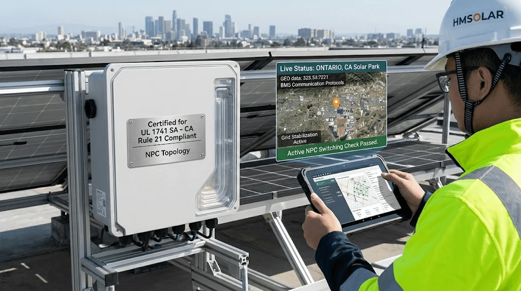
●Global Certifications: Complete hardware suites hold active certifications for IEC 62109-1/-2 (Safety), UL 1741 (Grid Support), IEEE 1547 (Interconnection), and CE-EMC directives, ensuring fast-tracked grid connection approvals in North America, Europe, and emerging Asia-Pacific markets.
FAQ
Q1: How do bi-directional inverters maintain operational stability in high ambient temperatures and coastal salt-mist environments?
Answer: HMSOLAR bi-directional inverters utilize isolated airflow cooling channels that separate power electronics from the heatsink exterior, preventing corrosive marine air from contacting internal control boards. Furthermore, internal components are coated with a military-grade conformal layer meeting IEC 61701 Severity 6 salt mist standards, ensuring zero corrosion-induced leakage currents or thermal derating up to 50°C ambient operating temperatures.
Q2: What are the packaging and maritime logistics protocols for bulk exports of heavy-duty power conversion systems?
Answer: International shipments of multi-kilowatt and megawatt-class inverters require ISPM 15-compliant fumigated wooden crates lined with multi-layer vacuum-sealed moisture barrier foil and industrial silica gel desiccants. Internal shock-absorbing EPE foam braces isolate the IGBT modules and heavy toroidal transformers from vibrational stress during multi-modal ocean freight and inland heavy-haul transport.
Q3: What is the standard engineering timeline and protocol adaptation scope for OEM/ODM grid-code customizations?
Answer: Custom firmware adaptations for regional utility interconnection codes (such as specific frequency-watt and voltage-watt response curves) typically require a 14-to-21-day engineering validation cycle. Our technical team collaborates directly with local grid operators to flash, simulate, and verify compliance parameters before mass production release, ensuring zero rejection during local witness testing.
Authoritative Endorsements & CTA
For utility-scale developers and institutional EPC contractors seeking bankable hardware and verified grid compliance, partnering with an experienced manufacturer ensures long-term asset security.
Contact our engineering team for a customized 10kW PV system layout and detailed BOM quote within 48 hours.