

Design Considerations for Multi-Megawatt Energy Storage Projects
2026 Technical Guide: Design Considerations for Multi-Megawatt Energy Storage Projects
Technical guide to multi-megawatt energy storage design. Evaluate liquid cooling, battery rack topology, safety systems, and utility battery integration.
Technical Engineering in Utility-Scale BESS Procurement
Deploying utility-scale energy storage assets entails specific engineering challenges, including thermal runaway propagation, auxiliary power losses, cell degradation mismatches, and grid-code compliance risks. For EPC contractors and utility developers, improper initial system architecture leads directly to reduced round-trip efficiency (RTE), premature capacity loss, and elevated operational costs over a 15-to-20-year project lifecycle.
Designing a multi-megawatt energy storage installation requires selecting cell topologies, thermal management circuits, and multi-tier battery management systems (BMS) that maintain thermal equilibrium across thousands of cells. This technical analysis examines the engineering trade-offs between liquid cooling and air cooling, rack-level electrical protection, containerized fire suppression protocols, and system-level integration parameters necessary to ensure financial performance and grid resilience.
Core Mechanisms of High-Capacity BESS Architecture
Designing megawatt energy storage systems involves precise electrical, thermal, and mechanical engineering across three primary layers: cell chemistry, rack topology, and containerized safety controls.
1. Cell Chemistry and Battery Rack Topology
Commercial multi-megawatt utility battery deployments utilize Lithium Iron Phosphate (LiFePO4) chemistry due to its structural thermal stability (decomposition temperature ≈270℃) and extended cycle life (> 6,000 cycles at 80% Depth of Discharge).
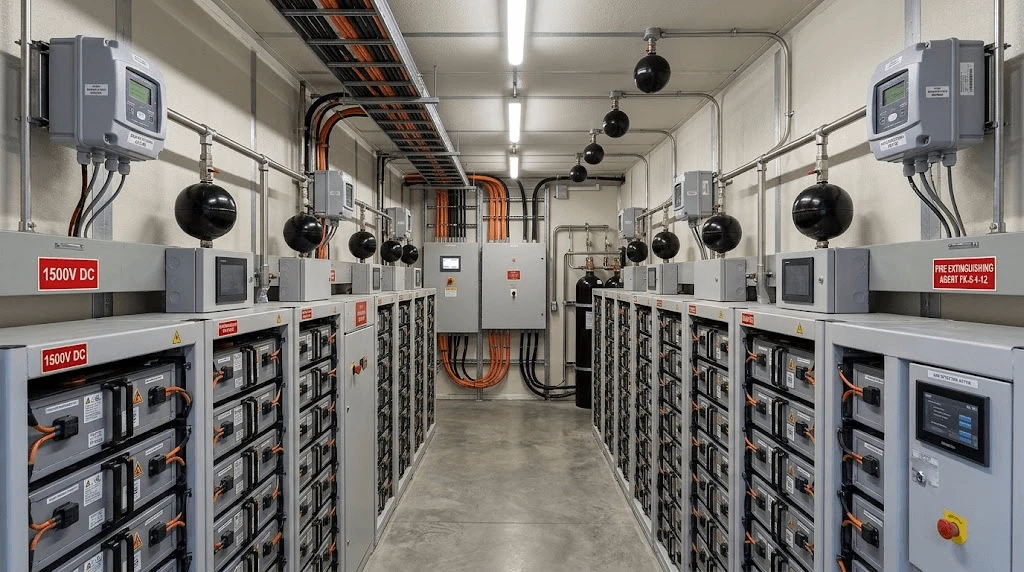
1500V DC Bus Architecture: Shifting from legacy 1000V DC architectures to 1500V DC topologies reduces balance-of-plant (BOP) cabling cross-sections, decreases DC distribution losses by up to 20%, and increases power density per enclosure.
Rack-Level Cell Stringing: Cells are configured in series-parallel arrangements to form modules, which are stacked into high-voltage racks. Advanced topologies integrate rack-level DC-DC converters or smart contactors to eliminate circulating currents between parallel strings, mitigating capacity loss caused by cell impedance drift.
2. Thermal Management: Liquid Cooling vs. Forced Air Cooling
Thermal gradient control is critical for preventing accelerated aging and localized thermal runaway.
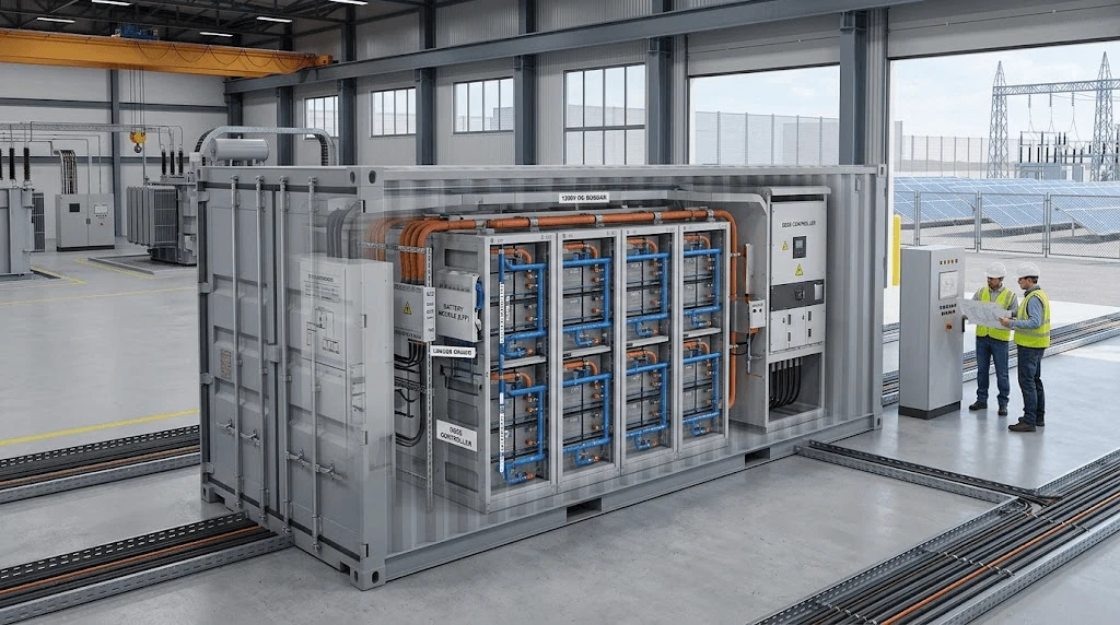
Liquid Cooling Mechanisms: Liquid-cooled plates containing water-glycol coolant interface directly with the aluminum casing of prismatic cells. Heat transfer coefficients for liquid loops exceed air-based systems by 20 to 30 times, keeping inter-cell temperature variances within ≤2.5℃ across the container enclosure.
Auxiliary Power Reduction: Liquid cooling lowers internal parasitic loads by up to 40% compared to air-conditioning units operating in ambient environments exceeding 40℃.
3. Multi-Tier BMS Protocols and Containerized Safety
Safety architectures require three-tier BMS configurations (Module Level → Rack Level → System Level) operating on high-speed CAN-bus or Ethernet protocols.
Gaseous and Thermal Sensing: Gas detectors monitor trace off-gassing (Carbon Monoxide, Hydrogen, and volatile organic compounds) prior to thermal runaway onset.
Integrated Fire Suppression: Fire response uses a two-stage approach: clean-agent gaseous suppression (such as FK-5-1-12) floods the enclosure to suppress early-stage electrical fires, while localized water-deluge manifolds provide direct cooling if cell temperatures exceed critical safety limits.
Industry Standards & ROI Impact
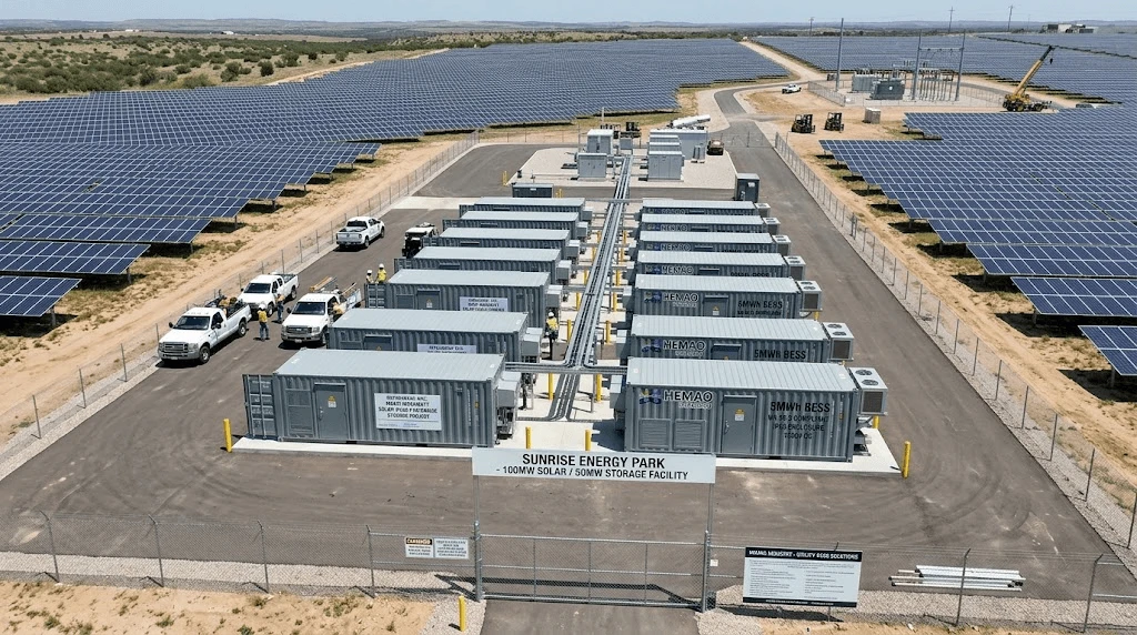
Thermal management and electrical configuration directly determine round-trip efficiency (RTE), capacity retention, and Levelized Cost of Storage (LCOS).
|
Technical Parameter |
Standard Air-Cooled BESS |
Advanced Liquid-Cooled BESS (Hemao Standard) |
Project Risk Mitigated |
|
Inter-Cell Temperature Variance |
≤5.0℃ |
≤2.5℃ |
Accelerated localized cell degradation, capacity loss |
|
System Energy Density (20ft Container) |
≈2.5 MWh−3.4 MWh |
≥5.0 MWh |
High civil works expenditure, large footprint requirements |
|
Auxiliary Power Consumption |
High (Continuous compressor fan load) |
Low (30%–40% reduction via variable pumps) |
Degraded Round-Trip Efficiency (RTE), high OpEx |
|
Expected Cycle Life (80% SOH) |
4,500 – 6,000 cycles |
8,000 – 10,000 cycles |
Premature battery augmentation or replacement costs |
|
Enclosure Protection Rating |
IP54 / NEMA 3R |
IP65 / NEMA 4X |
Dust ingress, high humidity, salt-spray corrosion |
LCOS and Financial Yield Dynamics
Cell degradation rate correlates with average operating temperature. Operating an LFP cell at 35℃ instead of 25℃ reduces usable cycle life by approximately 30% to 40%.
RTE Optimization: Liquid-cooled megawatt energy storage architectures achieve container-level Round-Trip Efficiency ratings of ≥89.5%, compared to 85.0% for conventional air-cooled containers.
Augmentation Timelines: Maintaining cell temperature uniformity within tight bands defers system capacity augmentation from Year 5 to Year 8 or Year 10, reducing capital expenditure reserves over the asset lifecycle.
System Integration & Compatibility
Utility battery assets must interface with existing grid infrastructure, photovoltaic arrays, and plant controllers.
Grid-Tied Integration Parameters
1. PCS and Hybrid Inverter Pairing: BESS containers integrate with 1500V central Power Conversion Systems (PCS). Communication between the Master BMS and PCS occurs via Modbus TCP or IEC 60870-5-104 protocols with response latencies below 20 milliseconds to provide primary frequency regulation.
2. Solar-Plus-Storage DC/AC Coupling:
DC-Coupled Architecture: Integrates storage directly onto the shared DC bus behind the inverter via high-efficiency DC-DC converters, maximizing capture of clipped solar energy.
AC-Coupled Architecture: Connects energy storage to the AC bus, providing flexibility for retrofit multi-megawatt projects and independent dispatch logic.
3. BMS and EMS Communication Alignment: System logic maps cell voltages, state of charge (SOC), state of health (SOH), and fault codes to centralized Energy Management Systems (EMS) to coordinate dispatch routines across multiple container units.
To explore complete storage system configurations and technical specifications, visit our Energy Storage Category.
Quality Control & Global Compliance
Exporting and commissioning utility battery assets requires verification of international safety standards and quality control protocols.
Key International Standards
UL 9540 & UL 9540A: Mandatory compliance for energy storage systems and thermal runaway fire propagation testing at the unit, module, rack, and container levels.
IEC 62619: Safety requirements for secondary lithium cells and batteries used in industrial and energy storage applications.
UN 38.3: Transport safety certification covering shock, vibration, thermal impact, and short-circuit testing for global ocean freight shipping.
NFPA 855: Standard for the Installation of Stationary Energy Storage Systems, governing minimum spatial separation distances, explosion venting, and hazard mitigation analysis.
FAQ
1. How does the liquid cooling system manage extreme ambient temperature swings (-30°C to +50°C) in desert or cold-climate utility sites?
The liquid cooling system incorporates bidirectional thermal management. Integrated PTC electric heaters preheat the glycol coolant loop during sub-zero ambient conditions to maintain cells above 10℃ before charging, preventing lithium plating.
In high ambient heat (+50℃), variable-frequency compressor chillers dynamically scale thermal exchange capacity to keep internal cell temperatures below 30℃, maintaining operation without thermal derating.
2. What are the shipping enclosure standards, weight limitations, and safety transport protocols for fully loaded 5MWh 20ft BESS containers?
Containerized BESS units are built in heavy-duty, ISO-certified 20ft high-cube shipping enclosures rated for structural loads up to 42,000 kg. Transportation complies with UN 38.3 standards, with battery modules locked into specialized vibration-damping rack mounts to prevent mechanical stress during ocean transit.
During transit, internal electrical contactors are physically isolated, and hazardous gas detection systems remain active or primed. Shipping procedures follow IMDG Code Class 9 dangerous goods compliance.
3. What are the technical parameters and lead times for custom EMS/BMS communication mapping and PCS integration on multi-megawatt projects?
Custom communication protocols (including IEC 61850, Modbus TCP, or DNP3 mapping) undergo Hardware-in-the-Loop (HIL) simulation testing before factory acceptance.
Factory customization of BMS parameter limits, control loops, and specialized PCS interfaces requires 3 to 4 weeks of software and system integration engineering. Factory Acceptance Testing (FAT) takes 10 to 14 days, followed by standard manufacturing and shipment lead times of 45 to 60 days depending on raw material allocation.
Engineering Consultation & BOM Requests
Designing a multi-megawatt energy storage project requires cell-level precision, thermal optimization, and code compliance. Contact our engineering team for a customized 2MW PV system layout and detailed BOM quote within 48 hours.


